19 jun 2024
My homelab journey and a tour of my network
ToC
Introduction
For the past few months, I’ve been blessed with working hand in hand with insanely knowleadgeable and skillful people. They have inspired me with their crazy setups and homelabs to get one of my own.
My friend Jason is my go-to guy for everthing PHP, Networking or pfSense related and on top of that he is a FOSS dev. He had the immesurable generosity of giving me a PCEngines router and troubleshooting with me, basically a whole weekend, my first attempt at bridging my router and getting this to work -which it didn’t since I was using an old HP Mini 110 Netbook with a NIC-to-USB interface that couldn’t handle my traffic and got buffer space errors-, so now that I have a proper router I can proceed with all of this.
On my roaster I also have Bert knowns the ins-and-outs of Linux like the palm of his hand. With years of experience in networking, and a long list of certs and tools at his disposal, he also has this talent of finding the most crazy projects and useful websites to play with. He has helped me greatly on moving from Proxmox to a more enterprisey approach to networking and virtualization, making me go down the RHEL, Podman and plain libvirt/qemu setup. He has also helped me greatly trying to figure out what went wrong post-mortem and checking the Switch’s ultimate config and I basically copied his Rocky lab.
So, with them backing me up and proving their insight and ideas, I’ve been hunting down networking and computing hardware these months to achieve this. It took me a while to provision me with all these equipment but here it is. This post acts as a sort of guide for myself and documentation of all of this.
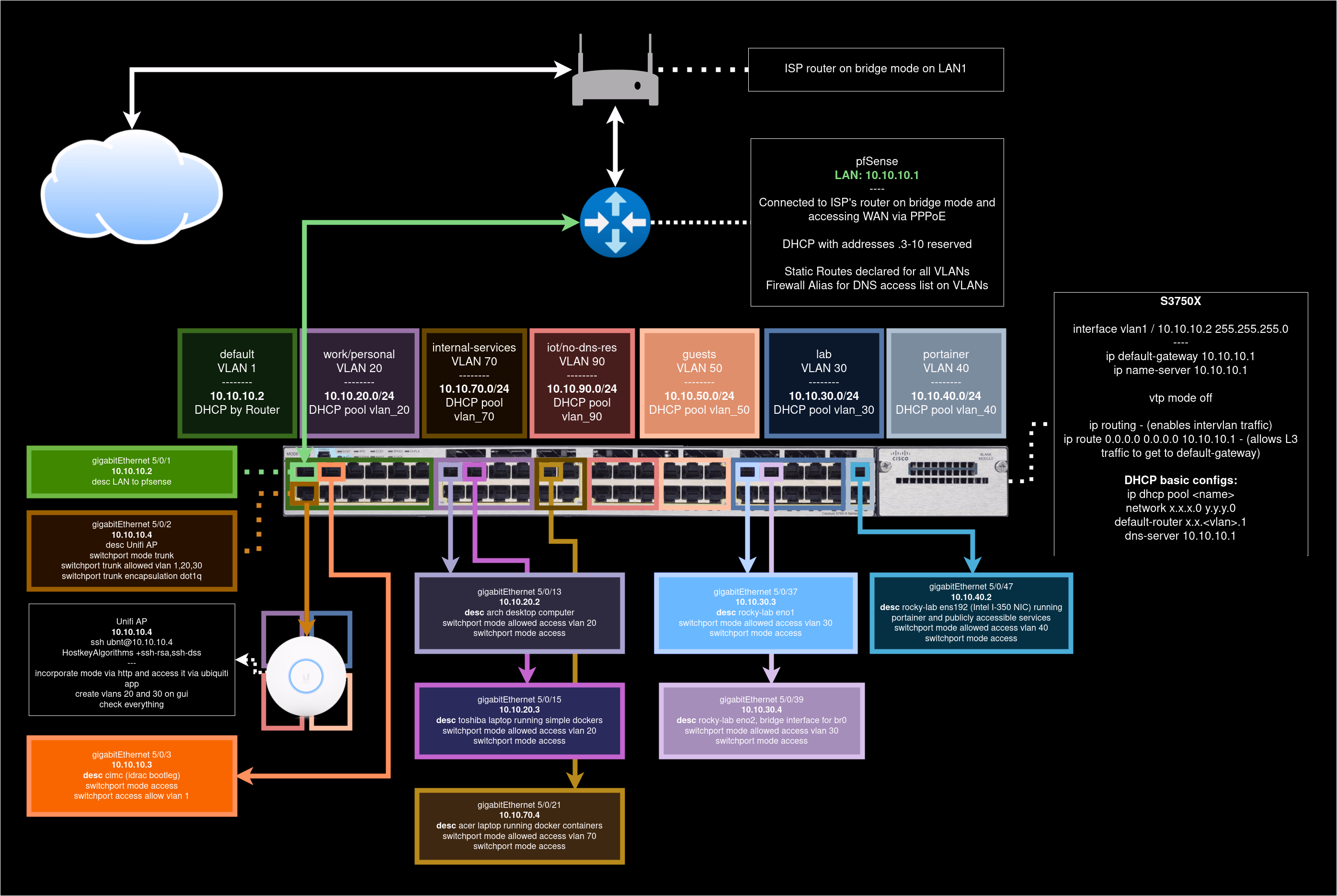
A brief tour on my lab and its network topology
My lab consists mainly of a couple of devices:
- PCEngines APU Router: 4 cores, 4 GB of RAM, 32G SSD. Its a little guy his red metallic enclosure, its a heavy weight champ. Your best ally on a bar fight. I’ll name it the Red Scare (Thanks again, Jason!).
- Cisco UCS C240 M4 LFF Rack Server: 2 Xeon processors, 64 GB of DDR4 ECC RAM, 3x6TB HDDs. It has 5 interfaces, counting its management one.
- Cisco Catalyst S3750X Switch: An L3 Switch sporting 48 ports with PoE.
- Ubiquiti Unifi Lite AP: Wireless Access Point from a top tier company. More than enough for my home network usage.
pfSense to the rescue
Jason was kind enough to leave a fresh install with the interfaces already assigned, but for documentation purposes, I’ll recreate what he did here:
Assigning and configuring interfaces
In your first pfSense setup, you’ll probably only have access to the CLI first, so assigning interfaces and IPs will be our first priority.
Enter the WAN interface name or 'a' for auto-detection:
(igc0, igc1, igc2 or a):
> igc0

Enter the LAN interface name or 'a' for auto-detection:
(igc1, igc2 or a):
> igc1

Enter the LAN interface name or 'a' for auto-detection:
(igc2 or a):
LAN
pfSense’s LAN default IP is 192.168.1.1/24. However, that doesn’t feel
enterprisey enough for me, and I find 10. addressess much easier to
memorize… they also look prettier in my opinion, but that is not a valid
reason lmao.
Following my topology, 10.10.10.1 should be my LAN IP address so I can reach
pfSense’s GUI to finalize this first setup. To accomplish that, we’ll do the
following once back to the CLI menu:
// ------ CLI menu ------
Enter an option:
> 2 # should be our already assigned LAN interface

Enter the number of interface you wish to configure:
> 2

Configure IPv4 address LAN via DHCP? (y/n):
> n

Enter the new LAN IPv4 address. Press <ENTER> for none:
> 10.10.10.1

(...)
Enter the new LAN IPv4 subnet bit count (1 to 32):
> 24

Do you want to enable the DHCP server on LAN? (y/n)
> y

For a WAN, enter the new LAN IPv4 upstream gateway address.
For a LAN, press <ENTER> for none:
> <ENTER> // We don't want a WAN obviously

Configure IPv6 address LAN via DHCP6? (y/n):
> n

Enter the new LAN IPv6 address. Press <ENTER> for none:
> <ENTER>
With this done, the next thing that pfSense will prompt us will be for a DHCP Server, so that is where we go next.
Setting up a DHCP Server
Last time I tried to setup this, my poor DIY router which was an HP Mini 110 Netbook with a NIC-USB interface hooked up, was not able to lease IPs for some reason, so when I tried to troubleshoot my network, this caused me a good amount of headaches. That is all gone thanks to this new PCEngines beast of a router, and having a DHCP server is, if not a must, a nice to have when setting up the more granular and coolest parts of pfSense, so I’ll create a DHCP server, reserving some of the IPs of key devices in my topology such as my CIMC, WiFi AP, and some other key things that may appear down the road.
To respect my topology, I’ll assign this to be handled by default vlan 1 on my
S3750X Switch, so interfaces that belong to this VLAN will get an IP via
pfSense’s DHCP server, which we’ll also have reserved the same way in its pool to avoid
overlapping IPs for some of these devices.
Do you want to enable the DHCP server on LAN? (y/n)
> y
Enter the start address of the IPv4 client address range:
> 10.10.10.10
Enter the end address of the IPv4 client address range:
> 10.10.10.254

Do you want to revert to HTTP as the webConfigurator protocol? (y/n)
> n
With this done, we’ll now move on to our pfSense web GUI, logging in with
default credentials admin and pfsense and take it from here.
WAN
Most of the time, bridge mode on a router will be a plug-and-play type of situation, but my ISP actually provides me with some WAN-PPPoE credentials that I’ll have to configure via the web GUI, so I’ll leave that to your imagination after the setup wizard.
With that done, we should be getting internet in a device plugged in directly to the LAN port of the Router, and they should get an IP. Now its a matter of configuring Static routes, some aliases and firewall rules for us to make this magnitudes easier on the switch’s side.
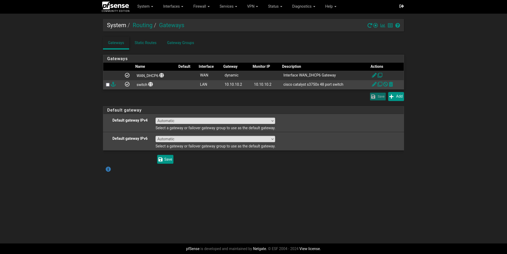
Adding a Gateway
Since this S3750X is an L3 switch, I can make it do the heavy lifting and leave only the outbound traffic and firewall management to pfSense so I can make the most out of both devices. To accomplish that, we must add a Gateway to our LAN interface so pfSense has somewhere to redirect outbound traffic.
For this System > Routing > Gateways and then Add will be the way to go in
the GUI. Interface will be LAN, Address Family will be IPv4, I’ll name it
switch and the Gateway will be address 10.10.10.2. Description can be
anything, so I’ll put something original like cisco catalyst s3750x switch.
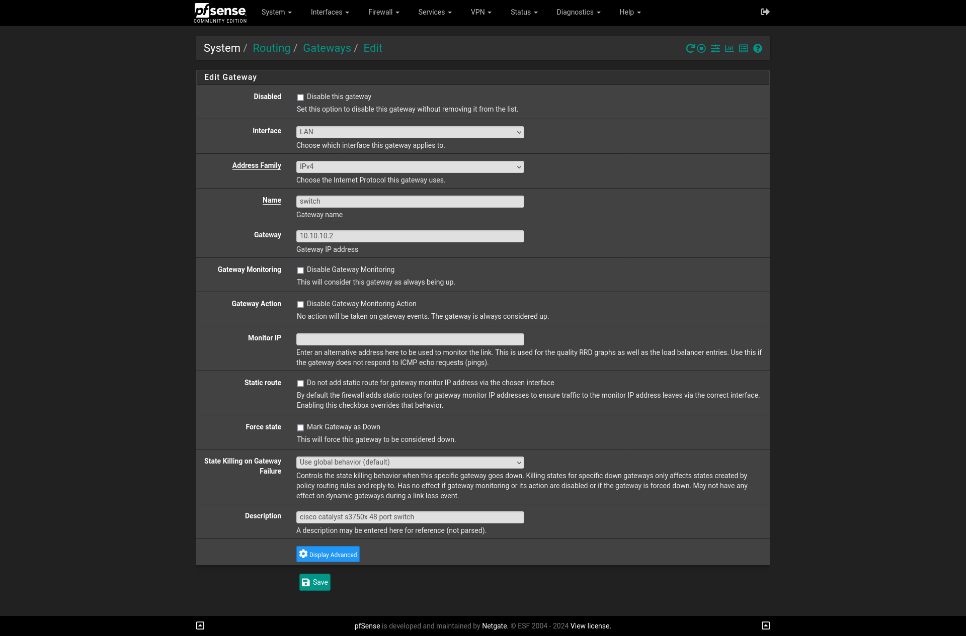
There are a couple other
options that may come in handy someday in the future like Monitor IP which
would be nice to set up with my FastEthernet interface so I can manage it and
monitor it that way. But for the time being, that is OK with me and all we want
is to get this thing up and working.
Setting up Static Routes
Looking at my topology, my VLANs are not in the same network, so these would be
unreachable from pfSense’s firewall, so packets from these 10.10.x.y addresses
wouldn’t get anywhere since there is no known way for the firewall on how to get
to these networks, much less how to handle its traffic because the switch’s
interfaces are not directly connected to the firewall. Hence, the need to setup
Static Routes. To make us of pfSense’s internal router, Static Routes for each one of my VLANs must be declared. A requirement to make Static Routes work is to add a Gateway that forwards the traffic to the firewall, so that is when declaring the Switch as one will come in handy.
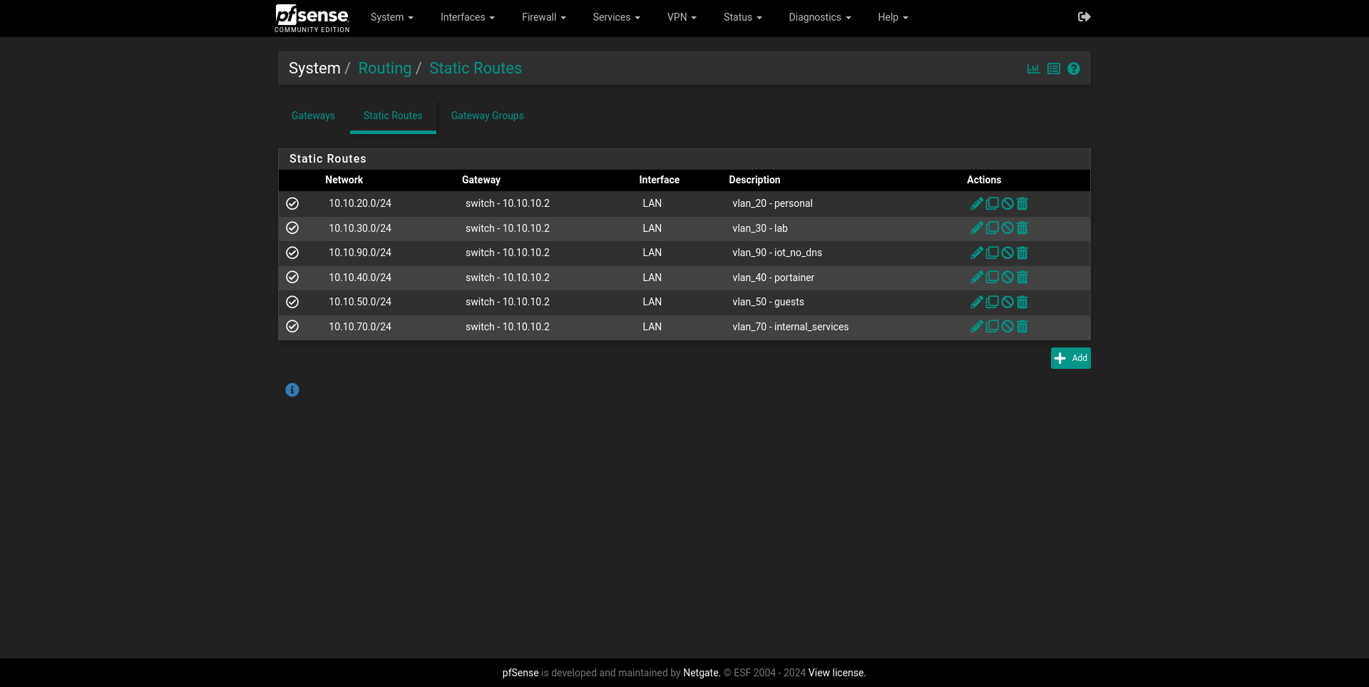
To get this going, System > Routing > Static Routes is where we want to then
Add.
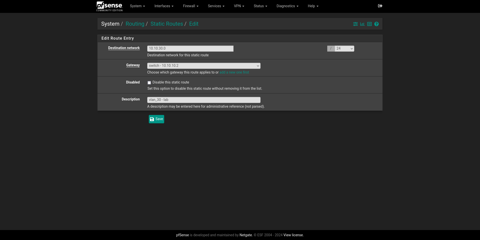
The setup is pretty easy, and we’ll just need to add the network and its subnet mask, alongside a description and the gateway it belongs to, which in this case is my S3750X L3 router. We can see all my VLANs now declared here.
Creating firewall aliases
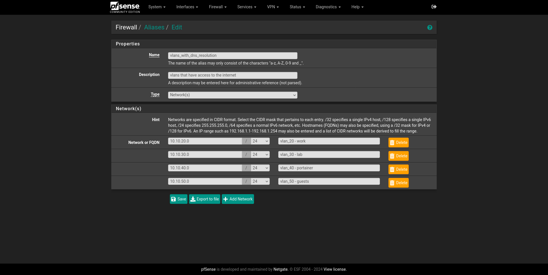
I don’t want all my VLANs to have internet access or to be accessed from outside my own network: things like IoT, Cameras and other internal services that I don’t want them to call home. Either way, aliases here can play a very convenient role, because now I can just create an alias containing the networks that my Static Routes have declared for each VLAN and group them. I’ll create one for all of them that should have internet.
We can achieve this going to Firewall > Aliases and selecting IP. There we
just Add a new alias of type network that declares our desired VLANs.
Playing by the rules
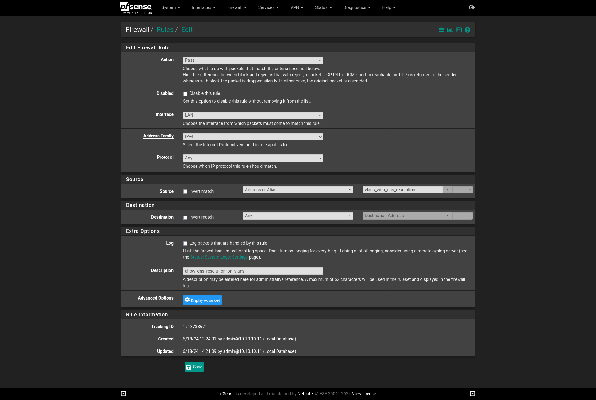
So, once we have this handy alias created, we must give it outbound access on
Firewall > Rules > LAN. The order here shouldn’t matter for our case, so just
adding one anywhere should do the trick. Firewall Rule Action should be Pass
as we want this traffic to be allowed. It should be for our LAN interface on
IPv4 and accept Any protocol.
Here is where our aliases do the heavy lifting, because in Source we can now
use Address or Alias and we can use the name which we declared it with.
Destination should also be Any as this traffic will go outbound.
In this current configuration, we should see something like this:
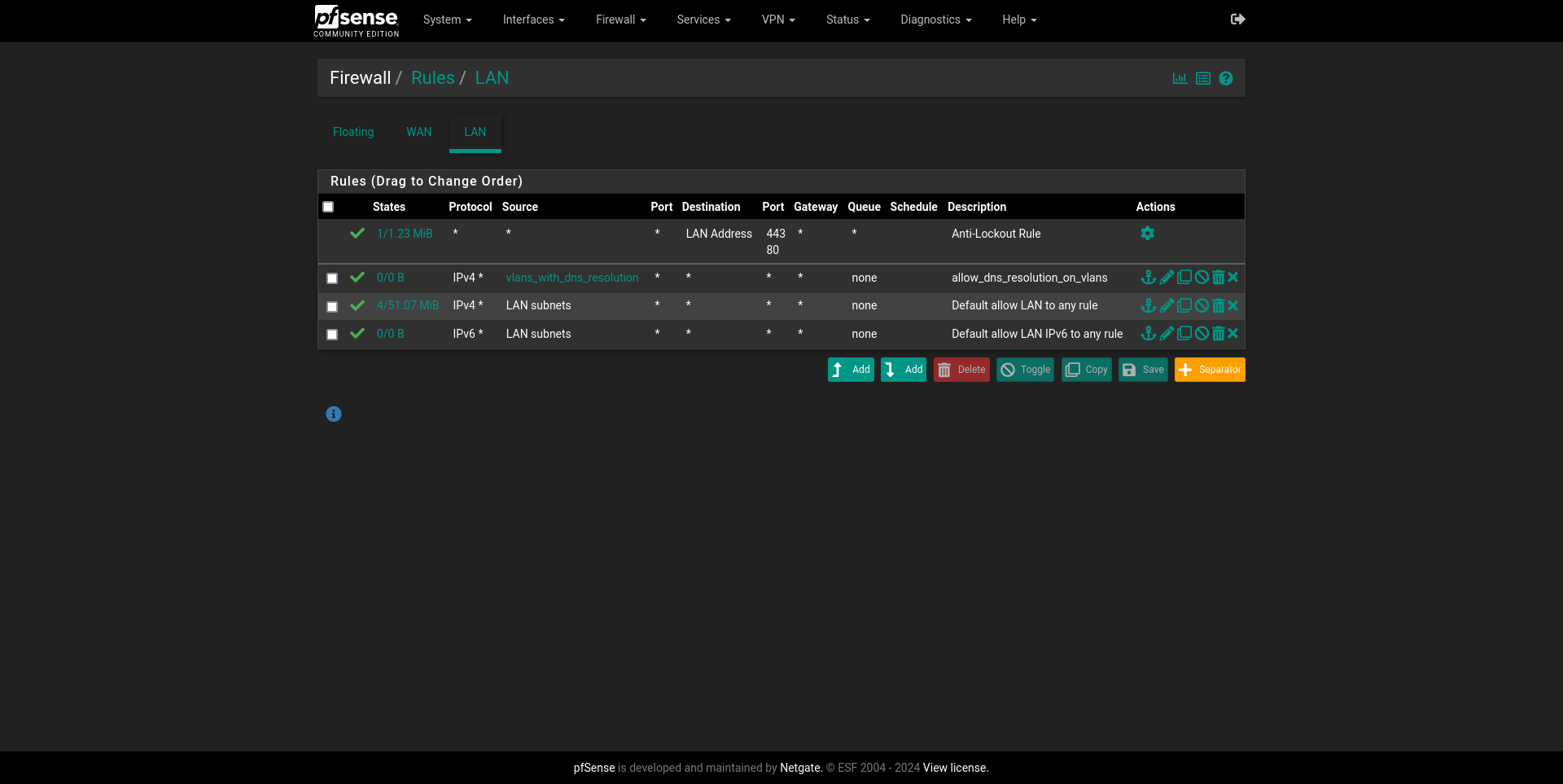
At this point, we should have a working connection if we are plugged in to our LAN interface directly.
Cisco IOS sucks
To avoid any sort of issues with lingering configurations which I’ve faced before, we’ll start from a blank slate. Here, a screen session will come very handy since we want to
Some general prep work
As mentioned before, we want the Switch to do the leg work since its L3. To achieve this and to work in harmony with pfSense settings, we want to achieve a couple key things. First, some superficial things like our Switch’s hostname:
Switch> en
Switch# conf t
Switch(config)# hostname S3750X- We need to give our
default vlan1an IP under pfSense’s LAN network. Following my topology, this will10.10.10.2. Doing it this way will accomplish a couple of things:- since this vlan is directly connected to pfSense, it will forward traffic to it if the destination is outside our LAN;
- devices plugged to its assigned interfaces will get an IP from our configured DHCP Server on pfSense, so in case of any VLAN going down, we can just plug in the device to one of these ports and still have internet access;
- for this same reason, it will also have key components of my network that I want them to be accessible at all times.
S3750X(config)# int vlan1
S3750X(config-if)# description routed port to pfsense lan
S3750X(config-if)# ip add 10.10.10.2 255.255.255.0
S3750X(config-if)# no shut- We must point our switch to pfSense for it to be our default-gateway and a DNS server. We want our router to handle both.
S3750X(config)# ip default-gateway 10.10.10.1
S3750X(config)# ip name-server 10.10.10.1- Finally, setup inter-VLAN routing using L3.
ip routingenables this in a quick and easy way. More granular control, like restricting given VLANs to actually communicate with other ones require ACLs, which I’ll tackle some day in the future.ip routewill tell how to actually handle traffic and get it to our default-gateway. This reads as redirect from any network to any other network to this gateway.
S3750X(config)# ip routing
S3750X(config)# ip route 0.0.0.0 0.0.0.0 10.10.10.1
During this whole section and troubleshooting of my first attempt, Jason found this great resource on how to enable L3 routing and make it work with pfSense. Although Static Routes is a given, we had some issues trying to get devices connected to assigned VLAN ports internet access and hit the router.
Now starts the actual fun part.
Creating VLANs
VLANs are logical separations of a single physical interface that can segment a
network into multiple. These operate on Layer 2 (Data-Link) and work adding
tags to network frames and create a virtual switch, also known as Switch
Virtual Interface (SVI) that can handle this traffic.
Cisco IOS CLI is a bit clunky, annoying to troubleshoot, and incredibely stiff,
but it gets the job done, and once you get used to their weird naming schemes
for their commands and tools -such as include, their own water dog take on
grep- it gets easier to navigate. This would be relatively self-explanatory.
We declare an interface vlanXX, its name and corresponding IP address,
alongside its subnet mask. Notice how it ends on .1 since this will also be
our default-gateway for both its corresponding DHCP server and DNS server.
To these VLANs we will also have to
S3750X(config)# int vlan20
S3750X(config-if)# name personal
S3750X(config-if)# ip add 10.10.20.1 255.255.255.0
Doing this for all subsequent VLANs in our topology is busy work, but easy.
Assigning interfaces to our VLANs
Now its a matter of assigning interfaces, by default, they all have access to
default vlan1 as stated before, so its a matter of checking at our topology
and using a very convenient command range, that will allow us to do tell
multiple interfaces where they belong to. To accomplish this we’ll use
switchport mode allowed vlan which takes VLAN’s IDs separated by a comma. This
will be important for when we setup our Wi-Fi AP.
S3750X(config)# int range gigabitEthernet 1/0/13-20 # vlan20
S3750X(config-if)# switchport mode access # this one should be set by default
S3750X(config-if)# switchport mode allowed vlan 1,20
With this done to the rest of interfaces which should be:
S3750X(config)# int range gigabitEthernet 1/0/21-24 # vlan70
S3750X(config)# int range gigabitEthernet 1/0/25-30 # vlan90
S3750X(config)# int range gigabitEthernet 1/0/31-36 # vlan50
S3750X(config)# int range gigabitEthernet 1/0/37-46 # vlan30
S3750X(config)# int range gigabitEthernet 1/0/46-48 # vlan40
We are now golden to proceed with DHCP on the Switch.
Creating DHCP Pools for our VLANs
Now, we want our VLANs to have their own DHCP pools so we don’t have to worry
about setting IPs in our clients. This is also straightforward enough. A pool is
declared and gets a name. I’ll just name it as our vlan interfaces to avoid
any confusions and having to remember their names. We declare a network that the
pool will lease IPs to the same way we declare IPs with ip add command, but
since now we are referring to the network itself, .0 is how we’ll declare
them as we did in our pfSense’s static routes. A default-router will be
necessary, this is our SVI’s IP address, and our DNS server should be also
pfSense. It can be another one, but I want to block ads network-wide so it makes
more sense to forward it to our red scare box.
S3750X(config)# ip dhcp pool <name> # vlan20
S3750X(config)# network 10.10.20.0 255.255.255.0
S3750X(config)# default-router 10.10.20.1
S3750X(config)# dns-server 10.10.10.1
Setting up the ground for Wi-Fi to work
With all this done, since our AP will have to deal with multiple VLANs, the port in which it is connected must also be able to read and handle our SVI’s tags. This can be done by trunking the port, which is basically segmenting a single physical interface to identify traffic of multiple VLANs, this is a great resource on the topic
S3750X(config)# int gigabitEthernet 1/0/2
S3750X(config-if)# switchport trunk encapsulation dot1q
S3750X(config-if)# switchport mode trunk
S3750X(config-if)# switchport trunk allowed vlan 1,20,30
Configuring SNMP Server
I want this to work like a clock, and that can only be achieved with proper monitoring. Luckily, setting up SNMP v2 is fairly straightforward. I won’t me messing around with v3 for the time being so just declaring the switch as the host and giving it a community string should be enough. I’ll leave this official documentation for future me.
S3750X(config)# snmp-server community <comm-string> ro
S3750X(config)# snmp-server host 10.10.10.2 version 2c <comm-string>
This can be then checked if its working by just performing a snmpwalk -v2c -c <comm-string> 10.10.10.2 on Linux.
Some extra considerations and TO-DOs
With this setup, since pfSense is not handling the VLANs, nor will get the tags because the Switch is doing all this work, restricting access between VLANs will have to be done on the Switch itself via access control lists. How its currently implemented, not all my VLANs can access the internet, but also in networks such as my Guest’s, I don’t want them to be able to access my other VLANs. Same thing with IoT and other services. I will tackle this in the near future as for now, all I want this is to work.
Furthermore, I need to re-do and document how I got access to the other forsaken end of Cisco Switch, its terrible web GUI. There are a couple ways to do it, and I always forget what are the default credentials are, or if they are needed at all in a factory reset Switch, but only God knows and that GUI doesn’t do much for me as it can barely display ports.
- Generate SSH keys for ease of access instead of doing it by Serial to USB connection for which I actually have a handy host declaration on my SSH config which I distinctly remember having a pain to connect to.
Host switch
    Hostname 10.10.10.2
    User admin
    KexAlgorithms +diffie-hellman-group1-sha1
    Ciphers aes128-cbc,3des-cbc,aes192-cbc,aes256-cbc
    PubkeyAcceptedAlgorithms +ssh-rsa
HostkeyAlgorithms +ssh-rsa- Setup
FastEthernetinterface to be able to manage the switch also.
Configuring our Unifi AP
I honestly don’t remember much of this process, but if everything went fine and I know have internet access on my wired connections, setting up this AP should be a matter of just resetting the device via the button under it, and connecting it to my bridged Ubuntu VM that also has the Unifi Controller running. Last time I did this, it never stopped blinking white, nor got an IP from my pseudo-router, so I had to resort to SSH to it directly. Also, since the controller is running on VLAN 30, I had to point it at this Ubuntu VM’s IP and port changing something in its CLI, which I think it was like this:
Host unifi
    Hostname 10.10.10.4
    User ubnt
    Passwd ubnt # default
    HostkeyAlgorithms +ssh-rsa,ssh-dss
Here I had to change its IP to access the Unifi Controller
info
set-inform http://10.10.30.X:8080/inform
Then its a matter of going to Unifi Controller’s GUI and recreating the VLANs on it, giving them SSIDs and all that good stuff, which I couldn’t document the first time, so I’ll do this next one.
Conclusion and special thanks
This has been quite the odissey, honestly. But in my journey, not only I’ve learned tons of things like virtualization, networking and got relatively profficient with Cisco equipment. Even picked up some carpentry skill because I built my own rack and handled a drill more than 10 minutes in my whole life, where I got lots of joy.
This wouldn’t have been possible at all without the help and generosity of my great colleagues, dear friends and mentors Jason, whose portfolio you can check out here and Bert, whose linkedin you can check.
Thanks to their infinite patience on my noob questions and I now sport an Frankenstein lab and network that contains both of their skills and preferences which I can call a setup of my own -sort of-.
See ya!